
| The boot lid's lining is secured by small "fir tree" pegs. These are a push-fit and can be released by pulling carefully on the lining at each side. Irritatingly, the grab-handle (not shown) is bolted to a rivetted nut that also bears on the lining. I found it possible to access the innards without detaching the lining from this. | |
|
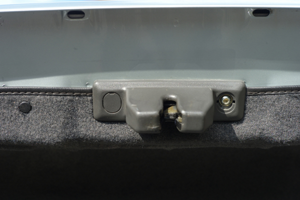 |
It should not be necessary to disturb the lock mechanism; however, if the lining pulls away, needing to be tucked back neatly, one end of the plastic finisher may be released by removing the finishing cap (with a finger nail) and unscrewing the securing bolt (Torx head) a few threads to allow the lining to be tucked back. The bolts secure the latch, so it would be undesirable to remove both, lest the latch's adjustment be lost. |
When the RHS fir tree pegs have been removed, the lining can be eased back from the hinge, allowing the plastic cover over the hinge to be released (another fir tree peg). I recommend using a pair of small wooden wedges (a dismembered clothes peg worked for me) to ease out the peg. This is not illustrated, as it should be obvious and would have been difficult to photograph.
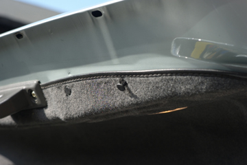
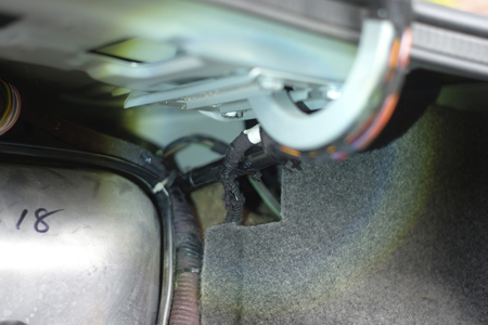
It is also necessary to release the lining of the rear wall of the boot. This is secured by two more "fir tree" pegs, using a suitable implement to effect a straight backward pull. I used an adjustable wire-stripper with right-angled jaws, set well-opened, but a pair of wide-bladed screwdrivers, if applied with care, would probably suffice. Having removed the pegs, the lining can be pulled astern.
 |
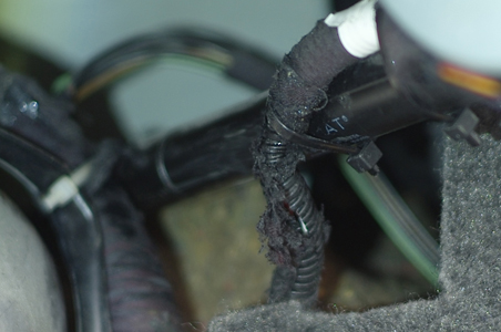
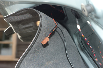
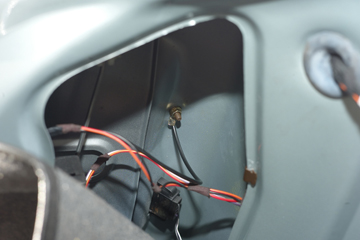
Here you can see that the securing pegs of the lid lining have been removed, the RH hinge uncovered and the rear wall lining pulled astern to reveal the route of the boot lid's wiring loom. The right-hand picture shows this in detail. | 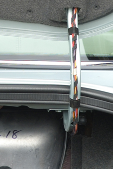 |
 |
 |
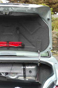
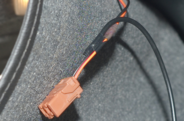
| Here, the lid lining has been drawn down to reveal a black box and its associated connector. This turned out to be the latch actuator. The connector is a simple push-fit. | 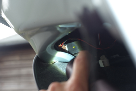 |
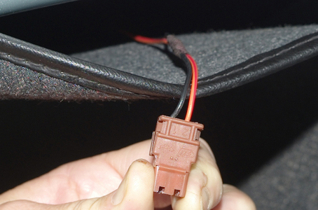 |
The black wire is the earth and failed continuity-testing with an ohm-meter to earth. Mercifully, the yellow-and-red connector carried a 9 volt positive emf. Accordingly, I decided not to track the black one through the loom, but instead to splice in another wire and earth it to a convenient point nearby. |
 |
 |
 |
September 2014