Continental R Spare wheel carrier
These pictures show the mechanism that raises and holds the spare wheel carrier in place. They were taken after the repair was effected, but you can infer reasonably clearly the situation that faced me when the lifting gear pulled away from the floor of the boot and fell off, to be lost somewhere on the Isle of Wight.
The pictures can be clicked to see larger versions for more detail.
This account relates to a 1993 car. There appears to be a plethora of different designs of spare wheel carrier amongst the SZ cars, but the lifting mechanism seems to be the same, although two different parts numbers are cited in the Parts List. I cannot guarantee that your car will have a compatible system.
You will need a pair of ½" AF spanners, one of which should preferably be a ring or socket to deal with locking nuts. A small pot-jack is also useful, to raise and hold the carrier into position during adjustments.
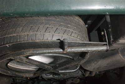 |
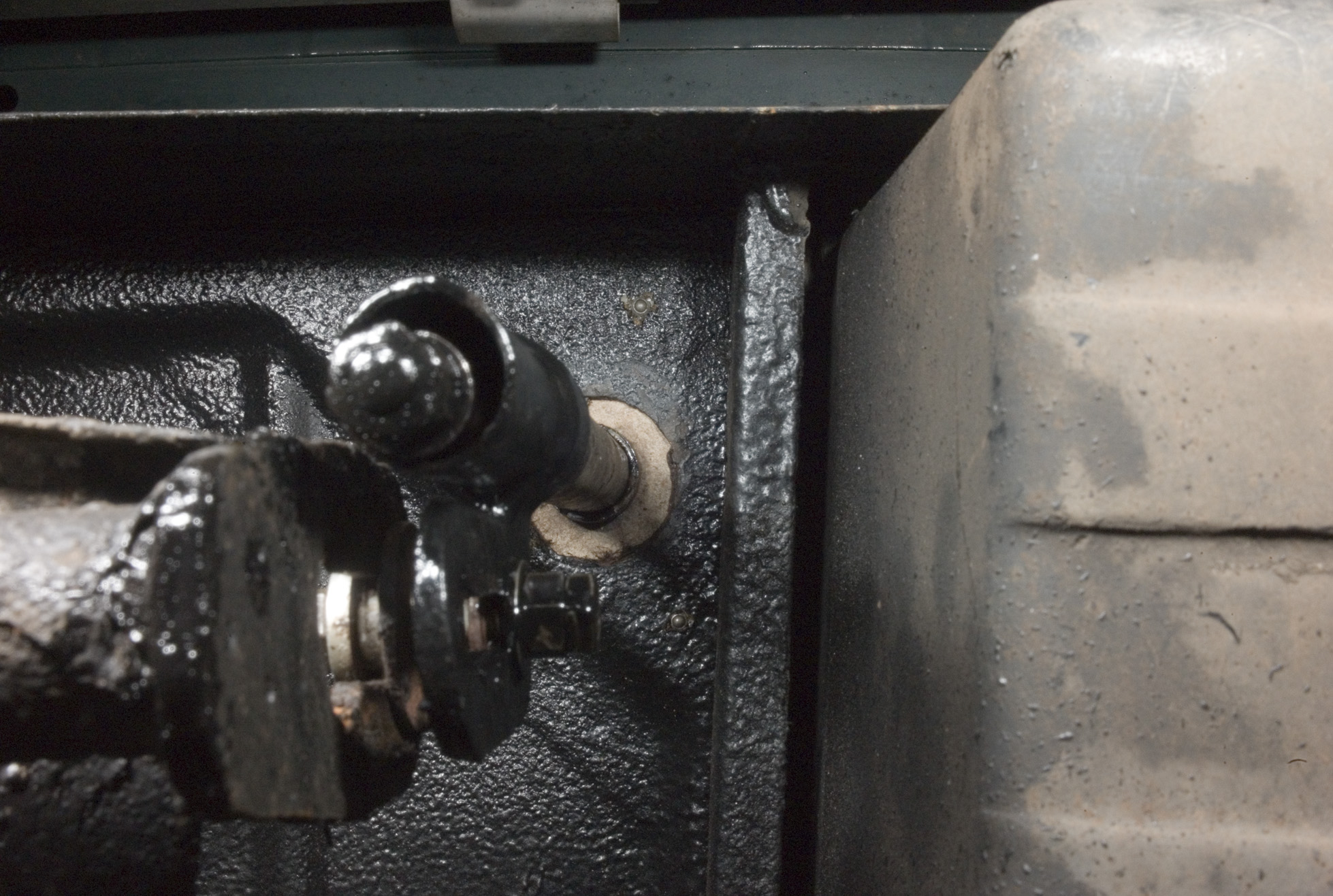
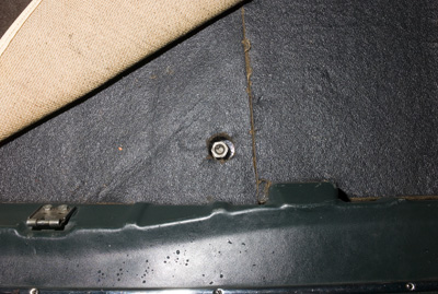
1. This is what the mechanism looks like from the rear of the car when assembled and fully raised. |
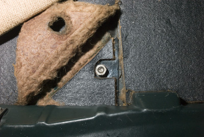
| 2. Detail, showing that the bolt joining the lifting screw assembly to the carrier frame passes through a keyhole slot in the latter's attachment lug.
I made up a short distance-piece (which cannot be seen in this photograph) from a length of ½" (?) gas pipe to provide a snug sliding fit in the keyhole slot, whilst separating the washers fitted on either side of the lug.
Note the washer and pair of locking nuts on the end of the vertical screw that just protrudes from the vertical tube; the screw must be fully home to expose the threads for these nuts. |
 |
 |
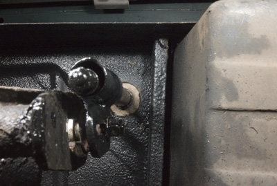
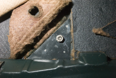
3. Seen from the outside, the two pairs of locking nuts, one pair securing the horizontal bolt to the lifting assembly's body and the other retaining the washer at the bottom end of the vertical lifting screw, can be clearly seen.
The box in the upper foreground is the battery box.
(Early versions of the carrier had no keyhole-slotted lug, but were attached directly to the lifting mechanism by a captive bolt inserted into the end of its tubular frame.) |
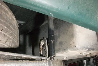
| 4. This photograph, taken from directly below, shows the large hole in the boot floor through which the original lifting assembly detached itself. As will be seen below, I made up a plate to fill the hole.
The components of the bolt assembly securing the carrier to the lifting assembly can be seen here: from left to right, bolt head (just visible through the keyhole), thick washer, short distance-piece, large washer, nut & washer (obscured by the lifting assembly's bracket) and finally, on the near side of that bracket, a washer, nut and locknut. |
 |
 |
5. Lifting the carpet in the boot, the only visible part of the lifting assembly is the nut secured to the top end of its lifting screw. |
| 6. Folding the underlay back reveals a further thickness of underlay, glued to the floor. |
 |
 |
7. When the triangle of underlay is peeled off, it ought to reveal a small (½-inch?) hole, through which the lifting screw passes. After the debacle, my car had a large hole (as seen from below in the photograph 4 above), but no lifting mechanism at all.
[Purists, please excuse the pop-rivets with which I secured a triangle cut from sheet-metal scrap, having drilled it to take the lifting screw, which I had separated from the lifting assembly's body.]
|
Fortuitously, it happened that a complete spare wheel carrier was being offered on Ebay at the time of my misfortune. Having assured myself that it was complete with lifting assembly, I bought this, detached the lifting assembly and disassembled it by removing the pair of locking nuts and washer from the lower end of the screw and winding out the screw. Having cleaned everything up, repainted the body and cut a triangle from sheet steel to fill in the hole, I found a bolt that fitted the slot in the body (5/16" if memory serves), together with a miscellany of nuts and washers, cut a short length of ½" gas pipe and filed its ends square to act as a distance piece in the keyhole slot of the carrier's body and assembled as follows.
- Assemble the bolt, its washers and distance-piece with one nut so as to be a snug sliding fit in the keyhole slot of the carrier. If necessary, file the distance-piece to such length as provides a snug fit.
- Remove the bolt from the keyhole slot and secure it to the slot in the lifting assembly. Leave the lock nut off at this stage.
- Apply a moderate amount of a suitable grease - I used Molyspring 204G - to the lifting screw and insert it from the top through a hole drilled in the reinforcing plate. Do not secure the plate to the boot floor at this stage.
Offer up the lifting assembly's body (it may be helpful to have an assistant, but it is possible to achieve single-handed) and screw up about half-way.
- Insert the carrier end of the bolt through the large end of the keyhole slot and slide it to the top of the keyhole slot. Screw up the lifting screw fully, drawing the spare wheel into its correct stowed position.
- If it appears that the top of the spare wheel is not pinched onto the underside of the boot floor, the position of the bolt in its slot in the lifting assembly's body needs to be adjusted upwards. In this case, use a suitable jack (a small pot-jack is ideal) to lift the carrier until the wheel is fully "home", whereupon the bolt will have slid downwards in the keyhole slot. Slacken the nut securing it to the lifting body and slide it up to take up any slack in the keyhole slot, then tighten the nut.
NOTE that in my case, the bolt is as far up as it can be in its slot. It may be as well to start with that arrangement and adjust downwards only if the wheel pinches prematurely (ie before the lifting screw is fully home).
- Attach and tighten the locknut. Remove the jack (if used).
- The end of the lifting screw should now protrude from the base of its tube. (If not, then the body of the assembly is not fully "home", in which case the bolt needs to be adjusted downwards as per para 5.) Attach its washer, nut and locknut.
- It is probably sound practice to apply moly grease sparingly between the lifting nut (above the boot floor) and the reinforcing panel. This may be done by winding the screw down until the carrier is caught on its safety hook, then winding a few turns more to raise the nut above the floor.
- When you are satisfied that the lifting assembly is correctly attached, secure the reinforcing plate appropriately. (I used three pop-rivets; you may prefer something more elegant.)
NOTE that the lifting assembly will not hang correctly (ie nearly vertical) unless its flange is towards the front of the car. The diagrams in the Parts List appear to have it the other way around. (Needless to say, I did it first according to what I thought "the book" said; then had to take it apart, reverse the bolt and do it all again.)
18 October 2013